Dosing Pump – Metering Pump
Metering Pump – Dosing Pump
A metering pump moves a precise volume of liquid in a specified time period providing an accurate volumetric flow rate. Delivery of fluids in precise adjustable flow rates is sometimes called metering. The term “metering pump” is based on the application or use rather than the exact kind of pump used, although a couple types of pumps are far more suitable than most other types of pumps.
Although metering pumps can pump water, they are often used to pump chemicals, solutions, or other liquids. Many metering pumps are rated to be able to pump into a high discharge pressure. They are typically made to meter at flow rates which are practically constant (when averaged over time) within a wide range of discharge (outlet) pressure. Manufacturers provide each of their models of metering pumps with a maximum discharge pressure rating against which each model is guaranteed to be able to pump against. An engineer, designer, or user should ensure that the pressure and temperature ratings and wetted pump materials are compatible for the application and the type of liquid being pumped.
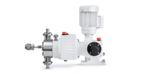
Most metering pumps have a pump head and a motor. The liquid being pumped goes through the pump head, entering through an inlet line and leaving through an outlet line. The motor is commonly an electric motor which drives the pump head.
:Piston pumps
Many metering pumps are piston-driven. Piston pumps are positive displacement pumps which can be designed to pump at practically constant flow rates (averaged over time) against a wide range of discharge pressure, including high discharge pressures of thousands of psi.
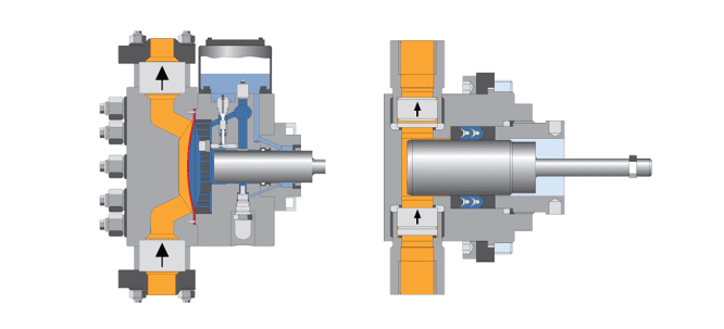
Piston-driven metering pumps commonly work as follows: There is a piston (sometimes called plunger), typically cylindrical, which can go in and out of a correspondingly shaped chamber in the pump head. The inlet and outlet lines are joined to the piston chamber. There are two check valves, often ball check valves, attached to the pump head, one at the inlet line and the other at the outlet line. The inlet valve allows flow from the inlet line to the piston chamber, but not in the reverse direction. The outlet valve allows flow from the chamber to the outlet line, but not in reverse. The motor repeatedly moves the piston into and out of the piston chamber, causing the volume of the chamber to repeatedly become smaller and larger. When the piston moves out, a vacuum is created. Low pressure in the chamber causes liquid to enter and fill the chamber through the inlet check valve, but higher pressure at the outlet causes the outlet valve to shut. Then when the piston moves in, it pressurizes the liquid in the chamber. High pressure in the chamber causes the inlet valve to shut and forces the outlet valve to open, forcing liquid out at the outlet. These alternating suction and discharge strokes are repeated over and over to meter the liquid. In the back of the chamber, there is packing around the piston or a doughnut-shaped seal with a toroid-shaped sphincter-like spring inside compressing the seal around the piston. This holds the fluid pressure when the piston slides in and out and makes the pump leak-tight. The packing or seals can wear out after prolonged use and can be replaced. The metering rate can be adjusted by varying the strokelength by which the piston moves back and forth or varying the speed of the piston motion.
A single-piston pump delivers liquid to the outlet only during the discharge stroke. If the piston’s suction and discharge strokes occur at the same speed and liquid is metered out half the time the pump is working, then the overall metering rate averaged over time equals half the average flow rate during the discharge stroke. Some single-piston pumps may have a constant slow piston motion for discharge and a quick retract motion for refilling the pump head. In such cases, the overall metering rate is practically equal to the pumping rate during the discharge stroke.
:Pumps used in high-pressure chromatography
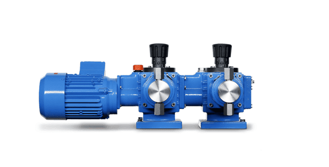
Pumps used in high-pressure chromatography such as HPLC and ion chromatography are much like small piston metering pumps. For wear resistance and chemical resistance to solvents, etc., typically the pistons are made of artificial sapphire and the ball check valves have ruby balls and sapphire seats. To produce good chromatograms, it is desirable to have a pumping flow rate as constant as possible. Either a single piston pump with a quick refill is used or a double pump head with coordinated piston strokes is used to provide as constant a pumping rate as possible.
: Diaphragm and peristaltic pumps
In order to avoid leakage at the packing or seal particularly when a liquid is dangerous, toxic, or noxious, diaphragm pumps are used for metering. Diaphragm pumps have a diaphragm through which repeated compression/decompression motion is transmitted. The liquid does not penetrate through the diaphragm, so the liquid inside the pump is sealed off from the outside. Such motion changes the volume of a chamber in the pump head so that liquid enters through an inlet check valve during decompression and exits through an outlet check valve during compression, in a manner similar to piston pumps. Diaphragm pumps can also be made which discharge at fairly high pressure. Diaphragm metering pumps are commonly hydraulically driven.
Peristaltic pumps use motor-driven rollers to roll along flexible tubing, compressing it to push forward a liquid inside. Although peristaltic pumps can be used to meter at lower pressures, the flexible tubing is limited in the level of pressure it can withstand.
: Possible problems
The maximum pressure rating of a metering pump is actually the top of the discharge pressure range the pump is guaranteed to pump against at a reasonably controllable flow rate. The pump itself is a pressurizing device often capable of exceeding its pressure rating, although not guaranteed to. For this reason, if there is any stop valvedownstream of the pump, a pressure relief valve should be placed in between to prevent overpressuring of the tubing or piping line in case the stop valve is inadvertently shut while the pump is running. The relief valve setting should be below the maximum pressure rating that the piping, tubing, or any other components there could withstand.
Liquids are only very slightly compressible. This property of liquids lets metering pumps discharge liquids at high pressure. Since a liquid can be only slightly compressed during a discharge stroke, it is forced out of the pump head. Gases are much more compressible. Metering pumps are not good at pumping gases. Sometimes, a metering or similar pump has to be primed before operation, i. e. the pump head filled with the liquid to be pumped. When gas bubbles enter a pump head, the compression motion compresses the gas but has a hard time forcing it out of the pump head. The pump may stop pumping liquid with gas bubbles in the pump head even though mechanically the pump is going through the motions, repeatedly compressing and decompressing the bubbles. To prevent this type of “vapor lock”, chromatography solvents are often degassed before pumping.
If the pressure at the outlet is lower than the pressure at the inlet and remains that way in spite of the pumping, then this pressure difference opens both check valves simultaneously and the liquid flows through the pump head uncontrollably from inlet to outlet. This can happen whether the pump is working or not. This situation can be avoided by placing a correctly rated positive pressure differential check valve downstream of the pump. Such a valve will only open if a minimum rated pressure differential across the valve is exceeded, something which most
A metering pump moves a precise volume of liquid in a specified time period providing an accurate volumetric flow rate.Delivery of fluids in precise adjustable flow rates is sometimes called metering. The term “metering pump” is based on the application or use rather than the exact kind of pump used, although a couple types of pumps are far more suitable than most other types of pumps.
Although metering pumps can pump water, they are often used to pump chemicals, solutions, or other liquids. Many metering pumps are rated to be able to pump into a high discharge pressure. They are typically made to meter at flow rates which are practically constant (when averaged over time) within a wide range of discharge (outlet) pressure. Manufacturers provide each of their models of metering pumps with a maximum discharge pressure rating against which each model is guaranteed to be able to pump against. An engineer, designer, or user should ensure that the pressure and temperature ratings and wetted pump materials are compatible for the application and the type of liquid being pumped.
Piston pumps – Metering Pumps (Motor Driven):
Most metering pumps have a pump head and a motor. The liquid being pumped goes through the pump head, entering through an inlet line and leaving through an outlet line. The motor is commonly an electric motor which drives the pump head.
Many metering pumps are piston-driven. Piston pumps are positive displacement pumps which can be designed to pump at practically constant flow rates (averaged over time) against a wide range of discharge pressure, including high discharge pressures of thousands of psi.
Piston-driven metering pumps commonly work as follows: There is a piston (sometimes called plunger), typically cylindrical, which can go in and out of a correspondingly shaped chamber in the pump head. The inlet and outlet lines are joined to the piston chamber. There are two check valves, often ball check valves, attached to the pump head, one at the inlet line and the other at the outlet line. The inlet valve allows flow from the inlet line to the piston chamber, but not in the reverse direction. The outlet valve allows flow from the chamber to the outlet line, but not in reverse. The motor repeatedly moves the piston into and out of the piston chamber, causing the volume of the chamber to repeatedly become smaller and larger. When the piston moves out, a vacuum is created. Low pressure in the chamber causes liquid to enter and fill the chamber through the inlet check valve, but higher pressure at the outlet causes the outlet valve to shut. Then when the piston moves in, it pressurizes the liquid in the chamber. High pressure in the chamber causes the inlet valve to shut and forces the outlet valve to open, forcing liquid out at the outlet. These alternating suction and discharge strokes are repeated over and over to meter the liquid. In the back of the chamber, there is packing around the piston or a doughnut-shaped seal with a toroid-shaped sphincter-like spring inside compressing the seal around the piston. This holds the fluid pressure when the piston slides in and out and makes the pump leak-tight. The packing or seals can wear out after prolonged use and can be replaced. The metering rate can be adjusted by varying the strokelength by which the piston moves back and forth or varying the speed of the piston motion.
A single-piston pump delivers liquid to the outlet only during the discharge stroke. If the piston’s suction and discharge strokes occur at the same speed and liquid is metered out half the time the pump is working, then the overall metering rate averaged over time equals half the average flow rate during the discharge stroke. Some single-piston pumps may have a constant slow piston motion for discharge and a quick retract motion for refilling the pump head. In such cases, the overall metering rate is practically equal to the pumping rate during the discharge stroke.
Pumps used in high-pressure chromatography:
Pumps used in high-pressure chromatography such as HPLC and ion chromatography are much like small piston metering pumps. For wear resistance and chemical resistance to solvents, etc., typically the pistons are made of artificial sapphire and the ball check valves have ruby balls and sapphire seats. To produce good chromatograms, it is desirable to have a pumping flow rate as constant as possible. Either a single piston pump with a quick refill is used or a double pump head with coordinated piston strokes is used to provide as constant a pumping rate as possible.
Manufacturers:
Germany
ProMinent
JESCO
LEWA
BRAN-LUEBBE
ALLDOS GRUNDFOS
SERA
Wepuko Pahnke
USA
Pulsafeeder Idex
France
Milton Roy LMI
D.K.M CLEXTRAL
UK
AxFlow
Japan
Iwaki
Nikkiso
Italy
EMEC
DOSEURO
ETATRON
SEKO
OBL
Injecta
Pompe Peroni S.p.A
O.M.GALLARATESI
Diaphragm and peristaltic pumps:
In order to avoid leakage at the packing or seal particularly when a liquid is dangerous, toxic, or noxious, diaphragm pumps are used for metering. Diaphragm pumps have a diaphragm through which repeated compression/decompression motion is transmitted. The liquid does not penetrate through the diaphragm, so the liquid inside the pump is sealed off from the outside. Such motion changes the volume of a chamber in the pump head so that liquid enters through an inlet check valve during decompression and exits through an outlet check valve during compression, in a manner similar to piston pumps. Diaphragm pumps can also be made which discharge at fairly high pressure. Diaphragm metering pumps are commonly hydraulically driven.
Peristaltic pumps use motor-driven rollers to roll along flexible tubing, compressing it to push forward a liquid inside. Although peristaltic pumps can be used to meter at lower pressures, the flexible tubing is limited in the level of pressure it can withstand.
Possible problems:
The maximum pressure rating of a metering pump is actually the top of the discharge pressure range the pump is guaranteed to pump against at a reasonably controllable flow rate. The pump itself is a pressurizing device often capable of exceeding its pressure rating, although not guaranteed to. For this reason, if there is any stop valvedownstream of the pump, a pressure relief valve should be placed in between to prevent overpressuring of the tubing or piping line in case the stop valve is inadvertently shut while the pump is running. The relief valve setting should be below the maximum pressure rating that the piping, tubing, or any other components there could withstand.
Liquids are only very slightly compressible. This property of liquids lets metering pumps discharge liquids at high pressure. Since a liquid can be only slightly compressed during a discharge stroke, it is forced out of the pump head. Gases are much more compressible. Metering pumps are not good at pumping gases. Sometimes, a metering or similar pump has to be primed before operation, i. e. the pump head filled with the liquid to be pumped. When gas bubbles enter a pump head, the compression motion compresses the gas but has a hard time forcing it out of the pump head. The pump may stop pumping liquid with gas bubbles in the pump head even though mechanically the pump is going through the motions, repeatedly compressing and decompressing the bubbles. To prevent this type of “vapor lock”, chromatography solvents are often degassed before pumping.
If the pressure at the outlet is lower than the pressure at the inlet and remains that way in spite of the pumping, then this pressure difference opens both check valves simultaneously and the liquid flows through the pump head uncontrollably from inlet to outlet. This can happen whether the pump is working or not. This situation can be avoided by placing a correctly rated positive pressure differential check valve downstream of the pump. Such a valve will only open if a minimum rated pressure differential across the valve is exceeded, something which most high-pressure metering pumps can easily exceed.
high-pressure metering pumps can easily exceed.
What is a dosing pump and how does it work?
What is a dosing pump?
A dosing pump is a small, positive displacement pump. It is designed to pump a very precise flow rate of a chemical or substance into either a water, steam or gas flow. A dosing pump will deliver this precise flow rate of chemical or other product by a number of different methods but it generally involves drawing a measured amount into a chamber and then injecting this volume of chemical into the pipe or tank being dosed. Dosing pumps are used in a variety of applications from agriculture, industry, manufacturing to medicine.
A dosing pump is generally quite small and is powered by either a small electric motor or air actuator. They are controlled either by an external control system or more commonly an internal pump controller that can alter the flow rate, the on/off function and also things like alarms and warnings for run dry, degassing and low product levels.
How do dosing pumps work?
Depending on the brand and model, a dosing pump functions in a variety of different methods. All these methods involve taking a measured amount of a chemical and then injecting that product into a pipe or similar vessel. There are a couple of major parts to a dosing pump setup:
- The chemical tank or container. The product that is being dosed,
- The foot valve. This is a one way valve that is attached to a suction line. It is placed into the drum of product and allows the pump to remain primed. It should have a weight on it so it remains in the bottom of the drum of product and sometimes it has a float switch attached to it so the pumps has an alarm activate if the product runs out.
- The pump itself. This can vary in size and materials but is generally a variety of chemical resistant plastic (PVC, PE or similar), rubbers or stainless steel. It has a suction line attached to the inlet and the dosing line attached to the suction. The mechanics of the pump can vary (see below).
- The dosing line this is generally a fairly
- rigid PVC or PE tube or a reinforced hose. Occasionally in steam, hot water or super high pressure applications the line can be stainless steel. This can have a variety of bleed, pressure relief, air release valves included into it but generally it is just a line.
The injector. At the point at which the product is injected into the product, there is an injector point. This is a one way valve so that when the dosing pump pushes an amount of product into the line it can overcome the pressure in the delivery pipe and allow the product out into the flow. Once a shot of product is released or the pump stops, the one way valve stops the liquid in the delivery line from going up the dosing line and damaging the pump. The injector also has a spout so that the product is delivered into the middle of the flow rather than the side wall. Over time certain products especially acids and oxidisers like chlorine or peroxide can corrode the walls of a pipe if released right at the edge of the stream. Releasing the product into the middle of the stream also creates a vortex which allows the product to mix properly too which is beneficial to ensure a proper reaction takes place.
- Control system. Occasionally there is a control system installed to ensure the dosing pump is accurate and turns on and off at particular times. This can be as simple as a timer or flow switch right through to a full SCADA or similar central .
Metering Pump Manufacturers List
Other common names for metering pumps include dispensing pumps, controlled-volume pumps, and proportioning pumps.
Users rely on these pumps in many industries because they produce extraordinarily accurate and repeatable results. They also love them because they send out a liquid cyclically on a consistent basis.Metering pumps are used for applications related to commercial vending, food and beverage processing, healthcare, irrigation, laboratory research, chemical engineering and processing, metalworking, milling, pharmaceuticals, plastic fabrication, petroleum and gas, water treatment, and more.Metering Pumps – Primary Fluid Systems Inc.
History Humans have been using pumps since at least the dominant years of Rome. The Romans, along with the ancient Indians, Persians, and Egyptians, used pumps in water wheels. They used water wheels to convert water power into energy.Another ancient people that most likely used pumps were the ancient Assyrians. It is likely that they used water screw pumps to irrigate the Hanging Gardens of Babylon. Many historians believe that Archimedes, the Greek polymath, came up with the design for his screw, the Archimedes screw, after visiting there.
During the Dark Ages, technology like this fell into disuse. It wasn’t until the Middle Ages that people began to take a renewed interest in pumps and what they could do. During the Middle Ages, the main thing that made scientists develop pump technology was the mining industry. As it grew in prominence, scientists and engineers looked for ways to make the process more efficient and profitable. That’s when they came up with the piston pump, also known as the suction pump, which works using atmospheric pressure. With early piston pumps, miners were able to force water from inaccessible areas into pump cylinders, then release it elsewhere out of outlet valves, so that they could mine those areas.
During this time, they developed a number of other pumps. One of the best sources on pumps from the 1500s comes from De Re Metallica, a 1556 work by Georgius Agricola.
During the Industrial Revolution, inventors and innovators developed new fluid pumps at a breathtaking pace. They did so in response to the demand put out by new mechanisms such as steam engines. Mainly during this time, manufacturers used pumps to control canal locks and various forms of water flow, though they did not control water flow directly.
In 1936, with the assistance of his father, an American named Robert Sheen invented the metering pump. He sketched and built his earliest pumps in his father’s basement. Sheen and his father, Milton Roy Sheen, worked together at what would later be called GE Water. Together, after selling some of their own products, they ventured out together and founded a company. They called it Milton Roy Pumps. The first metering pumps sold by the Sheens permitted flow rate adjustment but were given to inaccuracies because they permitted leaks. By dividing the pump body into two chambers with a diaphragm, later manufacturers were able to fix this problem. Later manufacturers also improved on the early metering pump by introducing pump materials like PTFE lining, that would not corrode. Early metering pumps used corrosive materials that dirtied the fluid they moved and weakened them.
Gorman-Rupp, a company based out of Ohio, began selling the first bellows type metering pump in the 1970s. Around this time, other manufacturers began producing the earliest diaphragm metering pumps featuring solenoid valves. By adding solenoid valves, engineers made it possible to operate metering pumps using electronics. While these pumps were easier to run, easier to keep healthy, and less costly, they could also operate at high speeds. Sometime later, engineers remedied this issue by implementing CNC dosing control.Metering pumps that operators use today offer the benefits that come along with advanced technology, like precision, control, and accuracy.
Design Metering pumps must meet a variety of unique and highly specialized needs, so manufacturers make them available in many sizes, materials, and configurations.
When designing a metering pump, manufacturers must decide on details like the type of liquid in use (fluid composition), maximum discharge pressure rating, flow rates, temperature ratings, motor capacity, and pump apparatus.
They must also decide on whether to build a pump structure that creates and works with variable displacement constant speeds or creates and works with fixed displacement variable speeds. This decision is directly impacted by other details like a pump’s individual motor capacity, stroke length and/or the degree to which the piston, membrane, or bellows can be extended.
Liquid Type It is important to understand the type of liquid that will flow through a pump for a few different reasons. First of all, most liquids are easy to compress, but if the liquid in use is a type that habitually produces gas bubbles, it will be much harder to compress. Paired with the wrong pump, such liquid may not get dispelled properly or at all. In addition, the type of liquid may affect the material construction of the pump.
Body Material Generally, metering pumps are made with durable metals, like stainless steel, or durable plastics, like PTFE. Some more than others, however, must have special qualities. For example, chemical metering pumps must be built with materials that exhibit the quality of extreme corrosion resistance.
Features No matter the details, all metering pumps are composed of a few important parts, including a pump head, a pump body, a variety of valves, a pumping mechanism, and a motor or engine.
The pump head is a cylindrical cavity, in which fluids reside before they are pumped. So that fluids can flow in and out of it, the pump head has both an inlet and an outlet. Connected to the inlet and outlet are check valves. Attached to the intake check valves are tubes or hoses, which connect it to a fluid reservoir.
The pump’s main body holds the process flow to which the fluid will be introduced. Tubes or hoses connect the outlet, or exhaust, valve on the other end to the main body of the pump. Note that each valve can only flow in one direction.
The pumping mechanism is found inside the pump head and will enact the motion that draws in and expels the fluid. This mechanism may be a piston, diaphragm, or bellows. Depending on a pump’s particular design, attached to this mechanism is either a manual pedal or a motor.The motor, which drives the pump head as a whole, is usually electric.
How They Work All pump types operate a little differently than one another, but most still mirror the basic operation of piston pumps. This two-part process begins with the suction, or intake stroke, which is when the piston first leaves the correspondingly shaped chamber in the pump head. When the piston is withdrawn, or, alternatively, when the bellows are extended, a vacuum is created which opens the inlet valve and pulls the fluid into the pump head. When the suction stops, the inlet closes.After this, an operator or motor extends the membrane piston, or, alternatively, compresses the bellows in towards the fluids. Both actions put pressure on the fluid, in order to compress and pressurize it as much as possible. This pressure forces the outlet valve open, where, due to displacement, the fluid is expelled.Users generally measure the rate at which a pump expels fluid as gallons per watt-hour, or GPH. GPH is also a reflection of a system’s efficiency.
Types Variable displacement constant speed pumps are metering pumps that control the amount of liquid being pumped at a time (flow rate) by changing the stroke, or displacement. They can have constant flow rates no matter the engine speed. These metering pumps can produce metered fluid on a continuous basis. Examples of machines that rely on variable displacement constant speed pumps including drink dispenser systems and dialysis machines.Fixed displacement variable speed pumps adjust flow rate based on motor speed, not stroke. They are simpler than variable displacement speed pumps and cannot transfer as much fluid as them. However, they provide consistent fluid flow rates during each rotation. Most often, people purchase fixed displacement variable speed pumps for use in commercial or industrial settings.
Positive displacement pumps move fluids from high pressure locations to low pressure locations.
Piston pumps use pistons, which are reciprocating, plunger-like cylinders. To pump fluid, they move in and out of a correspondingly shaped chamber in the pump head. The inlet and outlet valves are both connected to this chamber, called the piston chamber.
Diaphragm metering pumps use a flexible membrane made of Teflon, rubber, or thermoplastic, valves on either side, and, most likely, hydraulic power, to pump liquids. These valves may be any shut-off type that suits the job, such as butterfly valves, check valves, or flap valves. Liquid will not pass through diaphragm pump valves, meaning the liquid inside is sealed off from the outside world. For this reason, customers often choose diaphragm pumps to keep valves from leaking, especially those carrying sensitive, dangerous, toxic, or noxious fluids.
Bellows pumps work much like piston pumps, except that, in order to generate positive displacement, they use an accordion-style pleated body. Bellows pumps are clean and reliable.
Peristaltic pumps are a lesser known type of pump. Peristaltic pumps use motor-driven rollers to compress and move liquid inside flexible rubber tubing. They work in the same way that a human’s gastrointestinal tract works to move fluids through itself; they contract and relax.
Pneumatic metering pumps adjust flow rates using pneumatic actuator process signals.
Electronic metering pumps use electrical currents to give power to the actuators that stimulate pumping action. To adjust flow rate, they use electronic actuator signals. Because they are electronic, operators can control them with automated equipment and computer programming.
Micrometer adjustment screw pumps adjust flow rates using micrometer adjustment screws.
Chemical metering pumps are metering pumps designed specifically to move chemicals such as bases, slurries, corrosives, acids, and viscous fluids. Chemical metering pumps may also be called chemical dosing devices.
Fluid transfer pumps, also known as liquid pumps, are any metering pumps that move fluids. This group includes pumps regardless of their power source or flow rate adjustment mechanism. One of the most common types of fluid transfer pump is the water pump.
Dispensing pumps are metering pumps that dispense a predetermined amount of gas or liquid.
Centrifugal pumps move fluid without pulsation or squeezing with the help of a revolving disc.
Drum pumps are metering pumps designed specifically to pull fluids out of cylindrical containers like drums, tanks, and barrels.
Gear pumps move fluid by trapping it in between the teeth of rotating gears. Usually, they use two or three gears at once, and they are magnetically powered. Gear pumps work with applications requiring high pressure.
Small metering pumps are miniature pumps; they may be small in size, lightweight, and/or transporters of a particularly low flow. Small metering pumps can transmit fluid with the exact same amount of accuracy and precision of larger metering pumps.
Advantages
Metering pumps offer their users many advantages. First, they dispense fluid with high levels of accuracy and control. Second, they can work with harsh or hazardous fluids. Third, they are versatile; they can work with both high-pressure systems and low-pressure systems. Also, users can control them in many different ways, depending on their design.
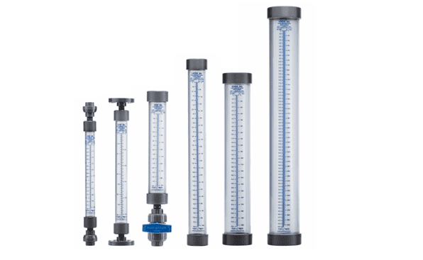
Accessories Examples of common metering pump accessories include foot valves, pressure control valves, injection valves, inline pressure relief valves, calibration cylinders, and pulsation dampeners.
Standards Metering pumps are beholden to a variety of different standard requirements, depending on the industry and location in which they are used. The American military, for example, requires that metering pumps meet Mil-Spec standards. Likewise, metering pumps used in food and beverage or healthcare in the United States must meet FDA standards.
On top of industry and location specific standards, you may want to make sure your metering pumps meet the standard guidelines of one or more organizations in the US or EU, such as ATEX, NEMA, and/or ANSI.
Things to Consider Metering pumps are incredibly useful but can be intimidating to shop for without professional assistance. For the best results, you need to consult with a high-quality metering pump manufacturer. Of course, finding a high-quality metering pump manufacturer can also be intimidating. To help find the right supplier for you, we’ve put together a list of some of those metering pump manufacturers we trust most. You can find their information by scrolling towards the middle of this page.From among them, find the right manufacturer for you by determining which one offers the services that most closely align with your needs, the best budget for you, the right delivery options (including delivery date), and the overall best customer service attitude. Good luck!
Many metering pumps are piston-driven. Piston pumps are positive displacement pumps which can be designed to pump at practically constant flow rates (averaged over time) against a wide range of discharge pressure, including high discharge pressures of thousands of psi.
Piston-driven metering pumps commonly work as follows: There is a piston (sometimes called plunger), typically cylindrical, which can go in and out of a correspondingly shaped chamber in the pump head. The inlet and outlet lines are joined to the piston chamber. There are two check valves, often ball check valves, attached to the pump head, one at the inlet line and the other at the outlet line. The inlet valve allows flow from the inlet line to the piston chamber, but not in the reverse direction. The outlet valve allows flow from the chamber to the outlet line, but not in reverse. The motor repeatedly moves the piston into and out of the piston chamber, causing the volume of the chamber to repeatedly become smaller and larger. When the piston moves out, a vacuum is created. Low pressure in the chamber causes liquid to enter and fill the chamber through the inlet check valve, but higher pressure at the outlet causes the outlet valve to shut. Then when the piston moves in, it pressurizes the liquid in the chamber. High pressure in the chamber causes the inlet valve to shut and forces the outlet valve to open, forcing liquid out at the outlet. These alternating suction and discharge strokes are repeated over and over to meter the liquid. In the back of the chamber, there is packing around the piston or a doughnut-shaped seal with a toroid-shaped sphincter-like spring inside compressing the seal around the piston. This holds the fluid pressure when the piston slides in and out and makes the pump leak-tight. The packing or seals can wear out after prolonged use and can be replaced. The metering rate can be adjusted by varying the strokelength by which the piston moves back and forth or varying the speed of the piston motion.
A single-piston pump delivers liquid to the outlet only during the discharge stroke. If the piston’s suction and discharge strokes occur at the same speed and liquid is metered out half the time the pump is working, then the overall metering rate averaged over time equals half the average flow rate during the discharge stroke. Some single-piston pumps may have a constant slow piston motion for discharge and a quick retract motion for refilling the pump head. In such cases, the overall metering rate is practically equal to the pumping rate during the discharge stroke.
Pumps used in high-pressure chromatography such as HPLC and ion chromatography are much like small piston metering pumps. For wear resistance and chemical resistance to solvents, etc., typically the pistons are made of artificial sapphire and the ball check valves have ruby balls and sapphire seats. To produce good chromatograms, it is desirable to have a pumping flow rate as constant as possible. Either a single piston pump with a quick refill is used or a double pump head with coordinated piston strokes is used to provide as constant a pumping rate as possible.
In order to avoid leakage at the packing or seal particularly when a liquid is dangerous, toxic, or noxious, diaphragm pumps are used for metering. Diaphragm pumps have a diaphragm through which repeated compression/decompression motion is transmitted. The liquid does not penetrate through the diaphragm, so the liquid inside the pump is sealed off from the outside. Such motion changes the volume of a chamber in the pump head so that liquid enters through an inlet check valve during decompression and exits through an outlet check valve during compression, in a manner similar to piston pumps. Diaphragm pumps can also be made which discharge at fairly high pressure. Diaphragm metering pumps are commonly hydraulically driven.
Peristaltic pumps use motor-driven rollers to roll along flexible tubing, compressing it to push forward a liquid inside. Although peristaltic pumps can be used to meter at lower pressures, the flexible tubing is limited in the level of pressure it can withstand.
The maximum pressure rating of a metering pump is actually the top of the discharge pressure range the pump is guaranteed to pump against at a reasonably controllable flow rate. The pump itself is a pressurizing device often capable of exceeding its pressure rating, although not guaranteed to. For this reason, if there is any stop valve downstream of the pump, a pressure relief valve should be placed in between to prevent overpressuring of the tubing or piping line in case the stop valve is inadvertently shut while the pump is running. The relief valve setting should be below the maximum pressure rating that the piping, tubing, or any other components there could withstand.
Liquids are only very slightly compressible. This property of liquids lets metering pumps discharge liquids at high pressure. Since a liquid can be only slightly compressed during a discharge stroke, it is forced out of the pump head. Gases are much more compressible. Metering pumps are not good at pumping gases. Sometimes, a metering or similar pump has to be primed before operation, i. e. the pump head filled with the liquid to be pumped. When gas bubbles enter a pump head, the compression motion compresses the gas but has a hard time forcing it out of the pump head. The pump may stop pumping liquid with gas bubbles in the pump head even though mechanically the pump is going through the motions, repeatedly compressing and decompressing the bubbles. To prevent this type of “vapor lock”, chromatography solvents are often degassed before pumping.Metering Pump SchematicIf the pressure at the outlet is lower than the pressure at the inlet and remains that way in spite of the pumping, then this pressure difference opens both check valves simultaneously and the liquid flows through the pump head uncontrollably from inlet to outlet. This can happen whether the pump is working or not. This situation can be avoided by placing a correctly rated positive pressure differential check valve downstream of the pump. Such a valve will only open if a minimum rated pressure differential across the valve is exceeded, something which most high-pressure metering pumps can easily exceed.
PLUNGER PUMPS DOSING PUMP • Low investment costs • Simple design • Easy maintenance DIAPHRAGM PUMPS DOSING PUMP: A leak-proof pump is the right choice whenever product purity or sterility are imperative or when toxic liquids must be handled. Flow Technology offers a wide range of hydraulically actuated Double diaphragm pumps.The design of the pump head ensures that the diaphragm cannot be damaged under critical conditions such as a blocked pipe or closed valves upstream or downstream of the pump.The freely defl ecting diaphragm makes the pump suitable for the metering of slurrieS. What is a dosing pump and how does it work? What is a dosing pump? A dosing pump is a small, positive displacement pump. It is designed to pump a very precise flow rate of a chemical or substance into either a water, steam or gas flow. A dosing pump will deliver this precise flow rate of chemical or other product by a number of different methods but it generally involves drawing a measured amount into a chamber and then injecting this volume of chemical into the pipe or tank being dosed. Dosing pumps are used in a variety of applications from agriculture, industry, manufacturing to medicine. A dosing pump is generally quite small and is powered by either a small electric motor or air actuator. They are controlled either by an external control system or more commonly an internal pump controller that can alter the flow rate, the on/off function and also things like alarms and warnings for run dry, degassing and low product levels. How do dosing pumps work? Depending on the brand and model, a dosing pump functions in a variety of different methods. All these methods involve taking a measured amount of a chemical and then injecting that product into a pipe or similar vessel. There are a couple of major parts to a dosing pump setup: 1. The chemical tank or container. The product that is being dosed, 2. The foot valve. This is a one way valve that is attached to a suction line. It is placed into the drum of product and allows the pump to remain primed. It should have a weight on it so it remains in the bottom of the drum of product and sometimes it has a float switch attached to it so the pumps has an alarm activate if the product runs out. 3. The pump itself. This can vary in size and materials but is generally a variety of chemical resistant plastic (PVC, PE or similar), rubbers or stainless steel. It has a suction line attached to the inlet and the dosing line attached to the suction. The mechanics of the pump can vary (see below). 4. The dosing line this is generally a fairly 5. rigid PVC or PE tube or a reinforced hose. Occasionally in steam, hot water or super high pressure applications the line can be stainless steel. This can have a variety of bleed, pressure relief, air release valves included into it but generally it is just a line. The injector. At the point at which the product is injected into the product, there is an injector point. This is a one way valve so that when the dosing pump pushes an amount of product into the line it can overcome the pressure in the delivery pipe and allow the product out into the flow. Once a shot of product is released or the pump stops, the one way valve stops the liquid in the delivery line from going up the dosing line and damaging the pump. The injector also has a spout so that the product is delivered into the middle of the flow rather than the side wall. Over time certain products especially acids and oxidisers like chlorine or peroxide can corrode the walls of a pipe if released right at the edge of the stream. Releasing the product into the middle of the stream also creates a vortex which allows the product to mix properly too which is beneficial to ensure a proper reaction takes place. 6. Control system. Occasionally there is a control system installed to ensure the dosing pump is accurate and turns on and off at particular times. This can be as simple as a timer or flow switch right through to a full SCADA or similar central
A metering pump moves a precise volume of liquid in a specified time period providing an accurate volumetric flow rate. Delivery of fluids in precise adjustable flow rates is sometimes called metering. The term “metering pump” is based on the application or use rather than the exact kind of pump used, although a couple types of pumps are far more suitable than most other types of pumps.
Although metering pumps can pump water, they are often used to pump chemicals, solutions, or other liquids. Many metering pumps are rated to be able to pump into a high discharge pressure. They are typically made to meter at flow rates which are practically constant (when averaged over time) within a wide range of discharge (outlet) pressure. Manufacturers provide each of their models of metering pumps with a maximum discharge pressure rating against which each model is guaranteed to be able to pump against. An engineer, designer, or user should ensure that the pressure and temperature ratings and wetted pump materials are compatible for the application and the type of liquid being pumped.
Most metering pumps have a pump head and a motor. The liquid being pumped goes through the pump head, entering through an inlet line and leaving through an outlet line. The motor is commonly an electric motor which drives the pump head.
Piston pumps : Many metering pumps are piston-driven. Piston pumps are positive displacement pumps which can be designed to pump at practically constant flow rates (averaged over time) against a wide range of discharge pressure, including high discharge pressures of thousands of psi.
Piston-driven metering pumps commonly work as follows: There is a piston (sometimes called plunger), typically cylindrical, which can go in and out of a correspondingly shaped chamber in the pump head. The inlet and outlet lines are joined to the piston chamber. There are two check valves, often ball check valves, attached to the pump head, one at the inlet line and the other at the outlet line. The inlet valve allows flow from the inlet line to the piston chamber, but not in the reverse direction. The outlet valve allows flow from the chamber to the outlet line, but not in reverse. The motor repeatedly moves the piston into and out of the piston chamber, causing the volume of the chamber to repeatedly become smaller and larger. When the piston moves out, a vacuum is created. Low pressure in the chamber causes liquid to enter and fill the chamber through the inlet check valve, but higher pressure at the outlet causes the outlet valve to shut. Then when the piston moves in, it pressurizes the liquid in the chamber. High pressure in the chamber causes the inlet valve to shut and forces the outlet valve to open, forcing liquid out at the outlet. These alternating suction and discharge strokes are repeated over and over to meter the liquid. In the back of the chamber, there is packing around the piston or a doughnut-shaped seal with a toroid-shaped sphincter-like spring inside compressing the seal around the piston. This holds the fluid pressure when the piston slides in and out and makes the pump leak-tight. The packing or seals can wear out after prolonged use and can be replaced. The metering rate can be adjusted by varying the strokelength by which the piston moves back and forth or varying the speed of the piston motion.
A single-piston pump delivers liquid to the outlet only during the discharge stroke. If the piston’s suction and discharge strokes occur at the same speed and liquid is metered out half the time the pump is working, then the overall metering rate averaged over time equals half the average flow rate during the discharge stroke. Some single-piston pumps may have a constant slow piston motion for discharge and a quick retract motion for refilling the pump head. In such cases, the overall metering rate is practically equal to the pumping rate during the discharge stroke.
Pumps used in high-pressure chromatography -Pumps used in high-pressure chromatography such as HPLC and ion chromatography are much like small piston metering pumps. For wear resistance and chemical resistance to solvents, etc., typically the pistons are made of artificial sapphire and the ball check valves have ruby balls and sapphire seats. To produce good chromatograms, it is desirable to have a pumping flow rate as constant as possible. Either a single piston pump with a quick refill is used or a double pump head with coordinated piston strokes is used to provide as constant a pumping rate as possible.
Manufacturers:Germany – sera GROUP – ProMinent – JESCO – LEWA – BRAN-LUEBBE – ALLDOS GRUNDFOS – Wepuko Pahnke – USA – Pulsafeeder Idex – Franca – Milton Roy LMI – D.K.M CLEXTRAL – AxFlow – Watson-Marlow – Japan – Iwaki – Nikkiso – Italy – EMEC – DOSEURO – ETATRON – SEKO – OBL – Injecta – Pompe Peroni S.p.A – O.M.GALLARATESI
Diaphragm and peristaltic pumps : In order to avoid leakage at the packing or seal particularly when a liquid is dangerous, toxic, or noxious, diaphragm pumps are used for metering. Diaphragm pumps have a diaphragm through which repeated compression/decompression motion is transmitted. The liquid does not penetrate through the diaphragm, so the liquid inside the pump is sealed off from the outside. Such motion changes the volume of a chamber in the pump head so that liquid enters through an inlet check valve during decompression and exits through an outlet check valve during compression, in a manner similar to piston pumps. Diaphragm pumps can also be made which discharge at fairly high pressure. Diaphragm metering pumps are commonly hydraulically driven.Peristaltic pumps use motor-driven rollers to roll along flexible tubing, compressing it to push forward a liquid inside. Although peristaltic pumps can be used to meter at lower pressures, the flexible tubing is limited in the level of pressure it can withstand. www.meteringpump.net
Possible problems : The maximum pressure rating of a metering pump is actually the top of the discharge pressure range the pump is guaranteed to pump against at a reasonably controllable flow rate. The pump itself is a pressurizing device often capable of exceeding its pressure rating, although not guaranteed to. For this reason, if there is any stop valve downstream of the pump, a pressure relief valve should be placed in between to prevent overpressuring of the tubing or piping line in case the stop valve is inadvertently shut while the pump is running. The relief valve setting should be below the maximum pressure rating that the piping, tubing, or any other components there could withstand. dosingpump.net
Liquids are only very slightly compressible. This property of liquids lets metering pumps discharge liquids at high pressure. Since a liquid can be only slightly compressed during a discharge stroke, it is forced out of the pump head. Gases are much more compressible. Metering pumps are not good at pumping gases. Sometimes, a metering or similar pump has to be primed before operation, i. e. the pump head filled with the liquid to be pumped. When gas bubbles enter a pump head, the compression motion compresses the gas but has a hard time forcing it out of the pump head. The pump may stop pumping liquid with gas bubbles in the pump head even though mechanically the pump is going through the motions, repeatedly compressing and decompressing the bubbles. To prevent this type of “vapor lock”, chromatography solvents are often degassed before pumping.www.dosingpump.net – www.meteringpump.net
If the pressure at the outlet is lower than the pressure at the inlet and remains that way in spite of the pumping, then this pressure difference opens both check valves simultaneously and the liquid flows through the pump head uncontrollably from inlet to outlet. This can happen whether the pump is working or not. This situation can be avoided by placing a correctly rated positive pressure differential check valve downstream of the pump. Such a valve will only open if a minimum rated pressure differential across the valve is exceeded, something which most high-pressure metering pumps can easily exceed.ofoghpump. dosingpump.net www.meteringpump.net
External links : Control the flow with metering pumps. Accuracy is critical when using controlled-volume metering pumps. Controlled-volume Metering Pump Hydraulic Institute Require high accurate, repeatable, and adjustable rate of flow. Siphon Pump metering is now repeatable with a high level of accuracy and control with flow control at the crown or bend of the siphon conduit. A controlled-volume is dispensed through an inline metering chamber by cyclically starting and stopping the siphon flow to replenish the holding canister. Siphons can be used in this manner to supply a variety of liquids above or away from the source. See Siphon article Siphon pump.
Metering Pump Manufacturers List
Other common names for metering pumps include dispensing pumps, controlled-volume pumps, and proportioning pumps.
Users rely on these pumps in many industries because they produce extraordinarily accurate and repeatable results. They also love them because they send out a liquid cyclically on a consistent basis.Metering pumps are used for applications related to commercial vending, food and beverage processing, healthcare, irrigation, laboratory research, chemical engineering and processing, metalworking, milling, pharmaceuticals, plastic fabrication, petroleum and gas, water treatment, and more.Metering Pumps – Primary Fluid Systems Inc.
History
Humans have been using pumps since at least the dominant years of Rome. The Romans, along with the ancient Indians, Persians, and Egyptians, used pumps in water wheels. They used water wheels to convert water power into energy.Another ancient people that most likely used pumps were the ancient Assyrians. It is likely that they used water screw pumps to irrigate the Hanging Gardens of Babylon. Many historians believe that Archimedes, the Greek polymath, came up with the design for his screw, the Archimedes screw, after visiting there.
During the Dark Ages, technology like this fell into disuse. It wasn’t until the Middle Ages that people began to take a renewed interest in pumps and what they could do. During the Middle Ages, the main thing that made scientists develop pump technology was the mining industry. As it grew in prominence, scientists and engineers looked for ways to make the process more efficient and profitable. That’s when they came up with the piston pump, also known as the suction pump, which works using atmospheric pressure. With early piston pumps, miners were able to force water from inaccessible areas into pump cylinders, then release it elsewhere out of outlet valves, so that they could mine those areas.
During this time, they developed a number of other pumps. One of the best sources on pumps from the 1500s comes from De Re Metallica, a 1556 work by Georgius Agricola.
During the Industrial Revolution, inventors and innovators developed new fluid pumps at a breathtaking pace. They did so in response to the demand put out by new mechanisms such as steam engines. Mainly during this time, manufacturers used pumps to control canal locks and various forms of water flow, though they did not control water flow directly.
In 1936, with the assistance of his father, an American named Robert Sheen invented the metering pump. He sketched and built his earliest pumps in his father’s basement. Sheen and his father, Milton Roy Sheen, worked together at what would later be called GE Water. Together, after selling some of their own products, they ventured out together and founded a company. They called it Milton Roy Pumps. The first metering pumps sold by the Sheens permitted flow rate adjustment but were given to inaccuracies because they permitted leaks. By dividing the pump body into two chambers with a diaphragm, later manufacturers were able to fix this problem. Later manufacturers also improved on the early metering pump by introducing pump materials like PTFE lining, that would not corrode. Early metering pumps used corrosive materials that dirtied the fluid they moved and weakened them.
Gorman-Rupp, a company based out of Ohio, began selling the first bellows type metering pump in the 1970s. Around this time, other manufacturers began producing the earliest diaphragm metering pumps featuring solenoid valves. By adding solenoid valves, engineers made it possible to operate metering pumps using electronics. While these pumps were easier to run, easier to keep healthy, and less costly, they could also operate at high speeds. Sometime later, engineers remedied this issue by implementing CNC dosing control.Metering pumps that operators use today offer the benefits that come along with advanced technology, like precision, control, and accuracy.
Design
Metering pumps must meet a variety of unique and highly specialized needs, so manufacturers make them available in many sizes, materials, and configurations.
When designing a metering pump, manufacturers must decide on details like the type of liquid in use (fluid composition), maximum discharge pressure rating, flow rates, temperature ratings, motor capacity, and pump apparatus.
They must also decide on whether to build a pump structure that creates and works with variable displacement constant speeds or creates and works with fixed displacement variable speeds. This decision is directly impacted by other details like a pump’s individual motor capacity, stroke length and/or the degree to which the piston, membrane, or bellows can be extended.
Liquid Type
It is important to understand the type of liquid that will flow through a pump for a few different reasons. First of all, most liquids are easy to compress, but if the liquid in use is a type that habitually produces gas bubbles, it will be much harder to compress. Paired with the wrong pump, such liquid may not get dispelled properly or at all. In addition, the type of liquid may affect the material construction of the pump.
Body Material
Generally, metering pumps are made with durable metals, like stainless steel, or durable plastics, like PTFE. Some more than others, however, must have special qualities. For example, chemical metering pumps must be built with materials that exhibit the quality of extreme corrosion resistance.
Features
No matter the details, all metering pumps are composed of a few important parts, including a pump head, a pump body, a variety of valves, a pumping mechanism, and a motor or engine.
The pump head is a cylindrical cavity, in which fluids reside before they are pumped. So that fluids can flow in and out of it, the pump head has both an inlet and an outlet. Connected to the inlet and outlet are check valves. Attached to the intake check valves are tubes or hoses, which connect it to a fluid reservoir.
The pump’s main body holds the process flow to which the fluid will be introduced. Tubes or hoses connect the outlet, or exhaust, valve on the other end to the main body of the pump. Note that each valve can only flow in one direction.
The pumping mechanism is found inside the pump head and will enact the motion that draws in and expels the fluid. This mechanism may be a piston, diaphragm, or bellows. Depending on a pump’s particular design, attached to this mechanism is either a manual pedal or a motor.The motor, which drives the pump head as a whole, is usually electric.
How They Work
All pump types operate a little differently than one another, but most still mirror the basic operation of piston pumps. This two-part process begins with the suction, or intake stroke, which is when the piston first leaves the correspondingly shaped chamber in the pump head. When the piston is withdrawn, or, alternatively, when the bellows are extended, a vacuum is created which opens the inlet valve and pulls the fluid into the pump head. When the suction stops, the inlet closes.After this, an operator or motor extends the membrane piston, or, alternatively, compresses the bellows in towards the fluids. Both actions put pressure on the fluid, in order to compress and pressurize it as much as possible. This pressure forces the outlet valve open, where, due to displacement, the fluid is expelled.Users generally measure the rate at which a pump expels fluid as gallons per watt-hour, or GPH. GPH is also a reflection of a system’s efficiency.
Types
Variable displacement constant speed pumps are metering pumps that control the amount of liquid being pumped at a time (flow rate) by changing the stroke, or displacement. They can have constant flow rates no matter the engine speed. These metering pumps can produce metered fluid on a continuous basis. Examples of machines that rely on variable displacement constant speed pumps including drink dispenser systems and dialysis machines.Fixed displacement variable speed pumps adjust flow rate based on motor speed, not stroke. They are simpler than variable displacement speed pumps and cannot transfer as much fluid as them. However, they provide consistent fluid flow rates during each rotation. Most often, people purchase fixed displacement variable speed pumps for use in commercial or industrial settings.
Positive displacement pumps move fluids from high pressure locations to low pressure locations.
Piston pumps use pistons, which are reciprocating, plunger-like cylinders. To pump fluid, they move in and out of a correspondingly shaped chamber in the pump head. The inlet and outlet valves are both connected to this chamber, called the piston chamber.
Diaphragm metering pumps use a flexible membrane made of Teflon, rubber, or thermoplastic, valves on either side, and, most likely, hydraulic power, to pump liquids. These valves may be any shut-off type that suits the job, such as butterfly valves, check valves, or flap valves. Liquid will not pass through diaphragm pump valves, meaning the liquid inside is sealed off from the outside world. For this reason, customers often choose diaphragm pumps to keep valves from leaking, especially those carrying sensitive, dangerous, toxic, or noxious fluids.
Bellows pumps work much like piston pumps, except that, in order to generate positive displacement, they use an accordion-style pleated body. Bellows pumps are clean and reliable.
Peristaltic pumps are a lesser known type of pump. Peristaltic pumps use motor-driven rollers to compress and move liquid inside flexible rubber tubing. They work in the same way that a human’s gastrointestinal tract works to move fluids through itself; they contract and relax.
Pneumatic metering pumps adjust flow rates using pneumatic actuator process signals.
Electronic metering pumps use electrical currents to give power to the actuators that stimulate pumping action. To adjust flow rate, they use electronic actuator signals. Because they are electronic, operators can control them with automated equipment and computer programming.
Micrometer adjustment screw pumps adjust flow rates using micrometer adjustment screws.
Chemical metering pumps are metering pumps designed specifically to move chemicals such as bases, slurries, corrosives, acids, and viscous fluids. Chemical metering pumps may also be called chemical dosing devices.
Fluid transfer pumps, also known as liquid pumps, are any metering pumps that move fluids. This group includes pumps regardless of their power source or flow rate adjustment mechanism. One of the most common types of fluid transfer pump is the water pump.
Dispensing pumps are metering pumps that dispense a predetermined amount of gas or liquid.
Centrifugal pumps move fluid without pulsation or squeezing with the help of a revolving disc.
Drum pumps are metering pumps designed specifically to pull fluids out of cylindrical containers like drums, tanks, and barrels.
Gear pumps move fluid by trapping it in between the teeth of rotating gears. Usually, they use two or three gears at once, and they are magnetically powered. Gear pumps work with applications requiring high pressure.
Small metering pumps are miniature pumps; they may be small in size, lightweight, and/or transporters of a particularly low flow. Small metering pumps can transmit fluid with the exact same amount of accuracy and precision of larger metering pumps.
Advantages
Metering pumps offer their users many advantages. First, they dispense fluid with high levels of accuracy and control. Second, they can work with harsh or hazardous fluids. Third, they are versatile; they can work with both high-pressure systems and low-pressure systems. Also, users can control them in many different ways, depending on their design.
Accessories
Examples of common metering pump accessories include foot valves, pressure control valves, injection valves, inline pressure relief valves, calibration cylinders, and pulsation dampeners.
Standards
Metering pumps are beholden to a variety of different standard requirements, depending on the industry and location in which they are used. The American military, for example, requires that metering pumps meet Mil-Spec standards. Likewise, metering pumps used in food and beverage or healthcare in the United States must meet FDA standards.
On top of industry and location specific standards, you may want to make sure your metering pumps meet the standard guidelines of one or more organizations in the US or EU, such as ATEX, NEMA, and/or ANSI.
Things to Consider
Metering pumps are incredibly useful but can be intimidating to shop for without professional assistance. For the best results, you need to consult with a high-quality metering pump manufacturer. Of course, finding a high-quality metering pump manufacturer can also be intimidating. To help find the right supplier for you, we’ve put together a list of some of those metering pump manufacturers we trust most. You can find their information by scrolling towards the middle of this page.From among them, find the right manufacturer for you by determining which one offers the services that most closely align with your needs, the best budget for you, the right delivery options (including delivery date), and the overall best customer service attitude. Good luck!
Many metering pumps are piston-driven. Piston pumps are positive displacement pumps which can be designed to pump at practically constant flow rates (averaged over time) against a wide range of discharge pressure, including high discharge pressures of thousands of psi.
Piston-driven metering pumps commonly work as follows: There is a piston (sometimes called plunger), typically cylindrical, which can go in and out of a correspondingly shaped chamber in the pump head. The inlet and outlet lines are joined to the piston chamber. There are two check valves, often ball check valves, attached to the pump head, one at the inlet line and the other at the outlet line. The inlet valve allows flow from the inlet line to the piston chamber, but not in the reverse direction. The outlet valve allows flow from the chamber to the outlet line, but not in reverse. The motor repeatedly moves the piston into and out of the piston chamber, causing the volume of the chamber to repeatedly become smaller and larger. When the piston moves out, a vacuum is created. Low pressure in the chamber causes liquid to enter and fill the chamber through the inlet check valve, but higher pressure at the outlet causes the outlet valve to shut. Then when the piston moves in, it pressurizes the liquid in the chamber. High pressure in the chamber causes the inlet valve to shut and forces the outlet valve to open, forcing liquid out at the outlet. These alternating suction and discharge strokes are repeated over and over to meter the liquid. In the back of the chamber, there is packing around the piston or a doughnut-shaped seal with a toroid-shaped sphincter-like spring inside compressing the seal around the piston. This holds the fluid pressure when the piston slides in and out and makes the pump leak-tight. The packing or seals can wear out after prolonged use and can be replaced. The metering rate can be adjusted by varying the strokelength by which the piston moves back and forth or varying the speed of the piston motion.
A single-piston pump delivers liquid to the outlet only during the discharge stroke. If the piston’s suction and discharge strokes occur at the same speed and liquid is metered out half the time the pump is working, then the overall metering rate averaged over time equals half the average flow rate during the discharge stroke. Some single-piston pumps may have a constant slow piston motion for discharge and a quick retract motion for refilling the pump head. In such cases, the overall metering rate is practically equal to the pumping rate during the discharge stroke.
Pumps used in high-pressure chromatography such as HPLC and ion chromatography are much like small piston metering pumps. For wear resistance and chemical resistance to solvents, etc., typically the pistons are made of artificial sapphire and the ball check valves have ruby balls and sapphire seats. To produce good chromatograms, it is desirable to have a pumping flow rate as constant as possible. Either a single piston pump with a quick refill is used or a double pump head with coordinated piston strokes is used to provide as constant a pumping rate as possible.
In order to avoid leakage at the packing or seal particularly when a liquid is dangerous, toxic, or noxious, diaphragm pumps are used for metering. Diaphragm pumps have a diaphragm through which repeated compression/decompression motion is transmitted. The liquid does not penetrate through the diaphragm, so the liquid inside the pump is sealed off from the outside. Such motion changes the volume of a chamber in the pump head so that liquid enters through an inlet check valve during decompression and exits through an outlet check valve during compression, in a manner similar to piston pumps. Diaphragm pumps can also be made which discharge at fairly high pressure. Diaphragm metering pumps are commonly hydraulically driven.
Peristaltic pumps use motor-driven rollers to roll along flexible tubing, compressing it to push forward a liquid inside. Although peristaltic pumps can be used to meter at lower pressures, the flexible tubing is limited in the level of pressure it can withstand.
The maximum pressure rating of a metering pump is actually the top of the discharge pressure range the pump is guaranteed to pump against at a reasonably controllable flow rate. The pump itself is a pressurizing device often capable of exceeding its pressure rating, although not guaranteed to. For this reason, if there is any stop valve downstream of the pump, a pressure relief valve should be placed in between to prevent overpressuring of the tubing or piping line in case the stop valve is inadvertently shut while the pump is running. The relief valve setting should be below the maximum pressure rating that the piping, tubing, or any other components there could withstand.
Liquids are only very slightly compressible. This property of liquids lets metering pumps discharge liquids at high pressure. Since a liquid can be only slightly compressed during a discharge stroke, it is forced out of the pump head. Gases are much more compressible. Metering pumps are not good at pumping gases. Sometimes, a metering or similar pump has to be primed before operation, i. e. the pump head filled with the liquid to be pumped. When gas bubbles enter a pump head, the compression motion compresses the gas but has a hard time forcing it out of the pump head. The pump may stop pumping liquid with gas bubbles in the pump head even though mechanically the pump is going through the motions, repeatedly compressing and decompressing the bubbles. To prevent this type of “vapor lock”, chromatography solvents are often degassed before pumping.Metering Pump SchematicIf the pressure at the outlet is lower than the pressure at the inlet and remains that way in spite of the pumping, then this pressure difference opens both check valves simultaneously and the liquid flows through the pump head uncontrollably from inlet to outlet. This can happen whether the pump is working or not. This situation can be avoided by placing a correctly rated positive pressure differential check valve downstream of the pump. Such a valve will only open if a minimum rated pressure differential across the valve is exceeded, something which most high-pressure metering pumps can easily exceed.
دوزینگ پمپها یا پمپ های مترینگ گونه ای از پمپ های جابجایی مثبت اند که قادرند مقدار دقیقی از سیال را پمپاژ نمایند و به همین جهت به آنها دوزینگ پمپ یا مترینگ پمپ گفته می شود. از آنجا که دبی پمپ های سانتریفوژ و روتاری بسته به فشار سیستم تغییر می کند، بنابراین هیچیک از پمپ های مذکور نمی تواند به عنوان دوزینگ پمپ مورد استفاده قرار گیرد. معمولاً تنها پمپ های پیستونی و پیستون دیافراگمی این امکان را دارند که در رده پمپ های دوزینگ قرار گیرند.
دوزینگ پمپ :دوزینگ پمپ دستگاهی است که مقدار دقیقی از مواد شیمیایی را تزریق می نماید. دبی این پمپ ها به صورت دستی و یا اتوماتیک و بسته به شرایط فرآیند قابل تغییر می باشد. این پمپ ها قادرند محدوده وسیعی از مواد شیمیایی حاوی اسیدها، سیالات خورنده و یا مایعات ویسکوز و اسلاری را پمپاژ نمایند. دقت کورس های رفت و برگشتی این پمپ ها بسیار بالا می باشد چرا که می بایست در هر کورس دوز صحیحی از سیال را پمپاژ نمایند. مترینگ پمپها عموماً در حالات زیر مورد استفاده قرار می گیرند:
الف) دبی های پایین که بر حسب ml/hr و یا GPH بیان شوند. ب) وقتی که فشار سیستم بالا است. پ) تزریق خیلی دقیق سیال مورد نیاز باشد. ت) تزریق سیال توسط رایانه، میکرو پروسسورها، DCS، PLC و یا شیرهای تناسبی کنترل می شود. ث) جاییکه مایعات خورنده، آتشزا و یا سیالات داغ انتقال داده می شود. ج) پمپاژ سیالات ویسکوز یا اسلاری ها
ساختار پمپهای دوزینگ : محرکه عموماً محرکه این پمپ ها یک الکتروموتور جریان متناوب AC دور ثابت می باشد. در بعضی موارد ممکن است الکتروموتورهای دور متغیر، موتورهای پنوماتیکی و یا هیدرولیکی نیز مورد استفاده قرار گیرد.
مکانیزم حرکت مکانیزم حرکت بگونه ای است که حرکت دورانی الکتروموتور به حرکت رفت و برگشتی تبدیل می گردد. غالب پمپ هایی که در صنایع مورد استفاده قرار می گیرد، اجزا مکانیزم حرکتی آنها درون روغن قرار می گیرد تا عملکرد مداوم سیستم تضمین گردد.
تنظیم دبی دبی پمپ با تغییر طول موثر کورس و یا تغییر سرعت کورس تنظیم می گردد. بیشتر دوزینگ پمپ ها از یک پیچ میکرومتر یا چیزی شبیه آن برای تنظیم دبی استفاده می کنند . میکرومتر می تواند با یک عملگر پنوماتیکی و یا الکترونیکی جایگزین گردد. در این حالت عملگر با سیگنالی که از سیستم دریافت می کند، دبی را به صورت اتوماتیک تنظیم می کند.
گذرگاه سیال Liquid End طراحی گذرگاه سیال و متریال آن با توجه به سرویس کاری پمپ و خصوصیات سیال مشخص می شود. مواردی همچون دما، دبی، ویسکوزیته، خورندگی سیال و فاکتورهای دیگر در طراحی موثر می باشند.
منحنی های مشخصه دوزینگ پمپها عمل پمپاژ توسط یک پیستون رفت و برگشتی انجام می شود. حرکت رفت و برگشتی سبب تولید دبی می شود که می توان به راحتی آن را توسط یک موج سینوسی نشان داد دبی پمپ برابر است با حاصلضرب مقدار جابجایی موثر پیستون در تعداد سیکل ها در واحد زمان.در دوزینگ پمپ ها بر خلاف پمپ های گریز از مرکز، تغییرات فشار تأثیر زیادی بر دبی ندارد. منحنی مشخصه دبی- کورس دوزینگ پمپ ها خطی می باشد. البته الزاماً به این معنی نیست که تنظیم ۵۰ درصد کورس برابر با ۵۰ درصد دبی می باشد. به خاطر اینکه خط کالیبر به طور همزمان از مبدا مختصات عبور نمی کند . با اندازه گیری دبی در دو بار تنظیم کورس و رسم خط مستقیمی که از دو نقطه می گذرد، می توان تغییرات دبی بر حسب تنظیم کورس را به صورت دقیق پیش بینی کرد. برای دوزینگ پمپ های صنعتی که به درستی نصب شده اند، دقت پیش بینی دبی در حدود ±۱ درصد می باشد. اگرچه دوزینگ پمپ ها عموماً می توانند برای دبی صفر تا حداکثر خود تنظیم شوند، اما دقت عمل آنها ممکن است کاهش یابد. عموماً سازندگان پمپ محدوده ۱۰ درصد تا ۱۰۰ درصد دبی را به عنوان محدوده عملکرد دقیق دستگاه مشخص می نمایند. اخیراً شرکت Milton Roy ادعا نموده است محدوده عملکرد دقیق دوزینگ پمپ مدل Centrac خود را به ۱درصد افزایش داده است. یعنی در هر نقطه بین دبی ۱ تا ۱۰۰ درصد، دقت دستگاه یکسان می باشد. محدوده دبی و فشار دوزینگ پمپ ها عموماً برای دبی های پایین مورد استفاده قرار می گیرند. ماکزیمم دبی هر پمپ با توجه به نسبت گیربکس، قطر پیستون و دور الکتروموتور تعیین می شود. معمولاً در محدوده دقیق دستگاه، حداقل دبی از ۴ر۰ گالون در ساعت یا ۵ر۱ لیتر بر ساعت شروع می شود و بزرگترین دوزینگ پمپ ها عموماً بیش از ۲۵۰۰ گالون بر ساعت یا ۹۵۰۰ لیتر بر ساعت دبی تولید نمی کنند. ماکزیمم فشار این پمپ ها تا PSI 30،۰۰۰ یا Bar ۲۰۰۰ بار گزارش شده است. اگر چه ممکن است بعضی سازنده ها بسته به نیاز مشتری با فشارهای بالاتر نیز تولید کرده باشند.
طرح های مختلف گذرگاه سیال گذرگاه سیال که به قطعات در تماس با سیال پمپ اطلاق می شود، بر مبنای شرایط کاری پمپ طراحی و انتخاب می گردد. دبی و فشار کاری بعلاوه خصوصیات فیزیکی و شیمیایی سیال مورد ملاحظه قرار می گیرد. در مواقعی که با سیالات آتشزا و سمی سروکار داریم، محافظت گذرگاه سیال از محیط اطراف نیز مساله ساز خواهد بود. تمامی گذرگاه های سیال چندین خصوصیت مشترک دارند: اول؛ با حرکت رو به عقب پیستون، سیال به داخل گذرگاه مکیده و با حرکت رو به جلو به بیرون فرستاده می شود. برای این منظور، در پمپ های دوزینگ در قسمت مکش و رانش شیرهای یکطرفه بکار می رود. هنگام عمل مکش، حرکت پیستون سبب می شود توپی شیر یکطرفه سمت مکش از روی نشیمن خود حرکت کند و سیال به داخل پمپ وارد شود. در همان موقع توپی شیر یکطرفه سمت رانش بر روی نشیمن خود فشرده می شود و امکان خروج سیال را غیر ممکن می سازد. هنگام کورس رانش، عکس این عمل اتفاق می افتد. شیرهای یکطرفه در طرح های مختلف ساخته شده اند. انتخاب نوع شیرها (مثلاً توپی یا سوپاپی) معمولاً با توجه به دبی پمپ انتخاب می شود و مسئولیت آن بر عهده سازنده پمپ می باشد. در مواقع پمپاژ اسلاری و یا مایعاتی که الیاف بلندی دارند بهتر است به جای استفاده از شیر یکطرفه نوع توپی تکی از شیر دوبل استفاده شود. چرا که اگر ذرات بین توپی و نشیمن گیر بیفتد آببندی شیر مختل می شود. بنابراین استفاده از شیر یکطرفه نوع توپی دوبل Double Ball Check Valve دقت و پایداری بیشتری دارد. از طرف دیگر، از آنجا که هر شیر یکطرفه ای حتی هنگامی که کاملاً باز می باشد مقداری مقاومت در مسیر جریان ایجاد می کند، در مواقعی که سیال ویسکوز می باشد استفاده از شیر یکطرفه تک در قسمت مکش ارجحیت دارد و باعث کاهش NPSHr می شود.
۱ پلانجر با آببندی پکینگی
این طرح تنها حالتی است که پیستون در تماس مستقیم با سیال فرایند می باشد (شکل ۴-۷). این طرح چندین مزیت دارد:
الف) قابلیت فشار و مکش رانش بالا ب) مقاومت دمایی بالا پ) NPSHr پایین
در این طرح آببندی پیستون از نوع پکینگ می باشد. پلانجر با آببندی پکینگی ساده و موثر است اما در بعضی کاربردها محدودیت هایی دارد. از آنجا که نشتی کنترل شده ای در پکینگها وجود دارد، این طرح نباید جهت سیالات شیمیایی آتشزا و سمی استفاده شود. علاوه بر این سایش بین پیستون و پکینگ سبب افزایش نشتی در مدت معینی می گردد. بنابراین باید به طور متناوب جهت حفظ بازده حجمی پکینگ ها تنظیم شوند. جهت جلوگیری از مشکلات نشتی باید از طرح دیافراگمی برای گذرگاه سیال استفاده کرد. پلانجر با آببندی پکینگی می تواند فشارهایی تا ۱۰۰۰ بار و دماهایی تا ۶۰۰ درجه فارنهایت را تحمل نماید.
۲ دیافراگم دیسکی Disc Diaphragm
طرح دیافراگم دیسکی برای گذرگاه سیال از یک دیافراگم تفلونی تشکیل شده است که مانعی بین سیال فرایند و پیستون می باشد حرکت رفت و برگشتی پیستون به سیال هیدرولیک وارد می شود که سبب حرکت دیافراگم به جلو و عقب می شود.فشار سیال هیدرولیک و فشار سیال فرایند هر دو یکسان است. در نتیجه فشار در دو طرف دیافراگم در تمام زمانها متعادل خواهد بود و سبب حذف تنش در آن می شود. دو صفحه کانتور مسیر حرکت دیافراگم را احاطه می کنند. سیال هیدرولیک و سیال فرایند از سوراخ های صفحه کانتور که به دقت طراحی شده اند عبور می کنند تا در تماس با دیافراگم باشند. شیرهای فشار شکن و پر کننده Refill حجم سیال هیدرولیک را کنترل می کنند. یک شیر تخلیه اتوماتیک هوا Automatic air bleed valve به طور پیوسته هوا را از سیال هیدرولیک خارج می کند. در این طرح، دیافراگم آببندی است. بنابراین انتخاب مناسبی است برای مایعات شیمیایی آتشزا، سمی و خورنده. جهت محافظت بیشتر، دیافراگم دوبل و سنسور نشتی استفاده می شود. اگرچه بخاطر استحکام بالای این طرح استفاده از طرح های محافظتی چندان متداول نیست.از آنجا که سیال فرایند می بایست از داخل سوراخ های نسبتاً کوچک صفحات کانتور عبور کند، این طرح برای اسلاری ها و سیالات ویسکوز بهترین انتخاب نیست.طرح دیافراگم دیسکی قابلیت تزریق تا فشار PSI 3500 یا بالاتر را دارد. دمای سیال ماکزیمم تا ۲۵۰ درجه فارنهایت امکان پذیر می باشد. همانطور که در بالا به آن اشاره شد، در این طرح از شیر فشار شکن و پرکننده استفاده می شود. در مواقعی که دیافراگم بنا به هر دلیلی نتواند در هنگام مکش پیستون به عقب حرکت کند، شیر پرکننده وارد عمل می شود و سیال هیدرولیک را وارد مجرا می کند. همچنین وقتی عمل مکش به طور موقت و یا دائم به خاطر مسائلی همچون بروز کاویتاسیون و یا بسته شدن ناگهانی شیر مکش و یا هر دلیل دیگری قطع شود، این شیر وارد عمل می شود و سیال هیدرولیک اضافی وارد مجرا مربوطه می کند. در نتیجه مجرا بیش از حد پر می شود و جهت جلوگیری از آسیب دیافراگم در کورس برگشت، صفحات کانتور مانع حرکت بیش از اندازه دیافراگم می گردند. در این حالت سیال هیدرولیک اضافی از شیر تخلیه خارج می گردد.صفحات کانتور محدب- مقعر می باشد و حرکت رفت و برگشتی دیافراگم را کنترل می کنند. این صفحه تعدادی سوراخ دارد که اجازه می دهد سیال در تماس با دیافراگم باشد. الگو و سایز این سوراخ ها باید به دقت مهندسی گردد تا استحکام کافی جهت نیروهای دیافراگم در فشارهای مختلف را داشته باشد. صفحه کانتور سمت سیال هیدرولیک در طول عملکرد خود مشکل خاصی ندارد و سیال هیدرولیک به راحتی از بین سوراخ های آن عبور می کند. اما صفحه کانتور سمت سیال فرایند محدودیت هایی از بابت شرایط سیال دارد. اسلاری ها و سیالات ویسکوز به راحتی نمی توانند از داخل سوراخ های صفحه کانتور عبور کنند. ضمن آنکه عبور سیال از داخل آن نیز سبب افت فشار و بالا رفتن NPSH پمپ می شود.
طرح دیافراگم مکانیکی این طرح توازن خیلی خوبی بین قیمت پایین و کیفیت عمل دارد. بخاطر نشتی صفر دیافراگم، در مواقعی که سیال گرانقیمت می باشد و یا دستورالعمل های زیست محیطی مطرح می باشد، استفاده از این طرح توجیه دارد. جهت پمپاژ اسلاری ها و سیالات ساینده، این طرح بهترین انتخاب است. جهت پمپاژ سیالات ویسکوز بالا و یا سیالاتی که شرایط سخت و مشکلی دارند از لحاظ اقتصادی طرح قابل قبولی است. در این طرح، پلانجر مستقیماً به دیافراگم متصل شده است . اتصال از طریق پیچ و کلامپ که از داخل دیافراگم و پلانجر عبور می کند، ایجاد می شود. حرکت الکتروموتور باعث حرکت رفت و برگشتی پلانجر می شود و در نتیجه باعث عمل مکش و رانش سیال از طریق دیافراگم می شود. فشار ماکزیمم در این طرح بالا نیست و حداکثر به ۱۵ بار خواهد رسید. با تعویض دیافراگم در مدت زمان معین، می توان عمر پمپ را افزایش داد. معمولاً هزینه های تعمیر و نگهداری سالانه این طرح بسیار پایین است.
طرح دیافراگم فلزی این طرحی بی همتا برای استفاده در شرایط بحرانی و کاربردهای فشار بالا مانند سکوهای نفت و گاز و صنایع حساس می باشد . این طرح به ویژه مواقعی استفاده می شود که دما و فشار محیط و سیال شیمیایی متغیر و پیچیده می باشد. اساس عمل این طرح مشابه سایر طرح های دیافراگمی می باشد. با این تفاوت که دیافراگم تلفونی (و یا ساخته شده با مواد معمولی) با یک آلیاژ فلزی مخصوص جایگزین شده است. این آلیاژ ویژه اجازه تولید فشارهای بالاتر از مواد معمولی را می دهد. همچنین طرح فلزی دیافراگم باعث می شود مایعات ساینده، ویسکوز و اسلاری ها با راندمان بهتری نسبت به طرح های استاندارد دیگر پمپاژ گردند. خیلی از سکویهای حفاری نفت به خاطر قابلیت اعتماد و طول عمر بیشتر، به این طرح احتیاج دارند.
۲ مکانیزم میل لنگ دورانی Polar Crank
این طرح عملکرد فوق العاده بهتری نسبت به مکانیزم میل لنگ خارج از مرکز دارد. یک چرخدنده مارپیچی دور بالا، دور الکتروموتور را کاهش و به میل لنگ دورانی منتقل می کند (شکل ۴-۱۹ و ۴-۲۰). یک میله رابط Connecting Rod که در دو سر خود یاتاقانهای کروی دارد از یک طرف به میل لنگ دورانی و از طرف دیگر به مجموعه Cross head و پیستون متصل است. در حالت دبی صفر یا به اصطلاح کورس صفر، محور میل لنگ دورانی و محور چرخدنده مارپیچ بر هم عمود هستند (شکل ۴-۱۹). در این حالت حرکت رفت و برگشتی مجموعه Cross head و پیستون تولید نمی شود و فقط میله رابط حول دایره میل لنگ دوران می کند. بسته به انحراف زاویه میل لنگ نسب به محور چرخدنده مارپیچ، کورس رفت و برگشتی شکل می گیرد. برای شکل گیری ماکزیمم کورس رفت و برگشتی، می بایست بیشینه زاویه ممکن بین میل لنگ و محور چرخدنده مارپیچی ایجاد شود. این زاویه نسبت به حالت کورس صفر (زاویه ۹۰ درجه بین میل لنگ و محور چرخدنده مارپیچی) اندازه گیری می شود. صرفنظر از میزان تنظیم طول کورس، این سیستم در انتهای کورس رانش، بیشترین نیرو را به سیال وارد می کند. این امر سبب می شود حداکثر سیال ممکن از گذرگاه سیال تخلیه گردد. همانطور که گفته شد، زاویه میل لنگ دورانی را می توان تغییر داد. این امر سبب افزایش یا کاهش طول کورس پیستون و در نتیجه تنظیم دبی از ۰ تا ۱۰۰ درصد می شود. معمولاً جهت کنترل دقیق دبی از میکرومتر دستی یا اتوماتیک استفاده می شود. به هر حال با توجه به نوع مکانیزم، کنترل دبی در این حالت نسبت به مکانیزم حرکتی میل لنگ خارج از مرکز، دقیقتر ومطمئن تر می باشد.
تجهیزات جانبی دوزینگ پمپ ها عملکرد صحیح سیستم پمپهای دوزینگ وابسته به انتخاب صحیح تجهیزات جانبی می باشد. در زیر به متداولترین تجهیزات جانبی این پمپ ها اشاره می شود.
شیرهای ایمنی Safety Relief Valves بیشتر سیستم های لوله کشی نیازمند شیرهای ایمنی برای محافظت از لوله ها در هنگام افزایش فشار غیر مجاز می باشد. اگرچه پمپ های دوزینگ شیر ایمنی برای محافظت از خود دارند، اما جهت محافظت لوله ها، کماکان نیاز به شیر ایمنی وجود دارد.
شیرهای Back Pressure از آنجا که پمپ های مترینگ باید دوز صحیحی از سیال را پمپاژ نمایند، در حالاتی که اختلاف فشار خط رانش و مکش کمتر از ۵ر۱ بار باشد، استفاده از این شیر توصیه می شود. این شیر باعث می شود دبی ناخواسته از پمپ به خاطر فشار کم خط رانش جریان نیابد.
تعدیل کننده های پالس جریان Pulsation Dampeners حرکت رفت و برگشتی پمپ های دوزینگ سبب می شود جریان خروجی به صورت پالسی باشد. این تعدیل کننده ها تا ۹۰ درصد پالس را از بین می برند. معمولاً این دستگاه تا فشار ۶۰ بار تولید می شود .
ستون کالیبراسیون اگرچه هنگامی که پمپی از کارخانه سازنده خریداری می شود، مشخصه های دبی و فشار آن قبلاً کالیبره می شود. اما هر چند وقت یکبار نیاز است پمپ در حال کار مجدداً تست و کالیبر گردد تا اطمینان حاصل شود دبی مورد نظر تأمین می شود.
صافی ها شیرهای یکطرفه پمپ های مترینگ باید از ورود ذرات و خرده ریزها توسط نصب صافی، محافظت شود. وقتی اسید سولفوریک غلیظ پمپاژ می کنید، تله لجن Sludge trap می بایست استفاده شود تا ذرات آلوده را به دام اندازد و محلول تمیز تحویل دهد.
0 comments